

A cylinder is too slow, or it stalls partway through the stroke. Someone swaps in a bigger bore, and the force problem goes away for a while. Then the move gets slower instead of faster, the compressor runs more, or the end of the stroke starts to bang hard enough to loosen the mounting bolts. The bore got bigger. The air supply, the load factor and the cushioning were never checked.
A cylinder is a simple part, but sizing it is a system check: the force at the pressure the cylinder actually sees, enough reserve to move the load at the speed you need, an air supply that can keep up, and a way to stop the load at the end of the stroke. This article walks through that pass, then looks at when an electric actuator fits the move better than air. The numbers below follow published manufacturer guidance. Your cylinder maker's sizing data governs.
Ferguson Automation is based in Braselton, GA, and works with plants and machine builders across the Southeast on mechanism design, reverse engineering and related mechanical work. The same check applies whether you are laying out a new station or replacing a cylinder that keeps falling short.
Force = pressure × area
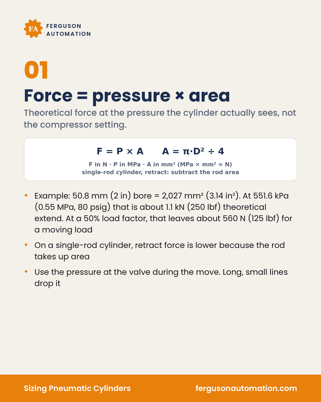
Theoretical force is the pressure the cylinder actually sees, multiplied by the piston area. It ignores friction, so it is an upper limit, not a working number.
F = P × A, with A = π · D² ÷ 4 (F in N, P in MPa, A in mm²; MPa × mm² = N)
D is the bore. On a single-rod cylinder, subtract the rod area from the piston area for the retract stroke, because the rod takes up part of the piston face on that side. On a single-rod cylinder, retract force is lower than extend force at the same pressure.
Example: a 50.8 mm (2 in) bore has a piston area of about 2,027 mm² (3.14 in²). At 551.6 kPa (0.55 MPa, 80 psig), that is about 1.1 kN (about 250 lbf) of theoretical extend force. At a 50% load factor, that leaves about 560 N (about 125 lbf) for a moving load. On retract, a 15.9 mm (5/8 in) rod takes up part of the piston face, and theoretical force drops to about 1.0 kN (about 227 lbf).
The pressure that matters is the pressure at the cylinder during the move, not the compressor setting or the reading at the main header. Flow losses through long, small-bore lines, fittings and valves drop the pressure the piston sees, and that loss directly reduces force and speed. Size from the pressure the regulator can hold at the valve while the cylinder is moving, and keep some margin between that and the supply.
Leave a load factor
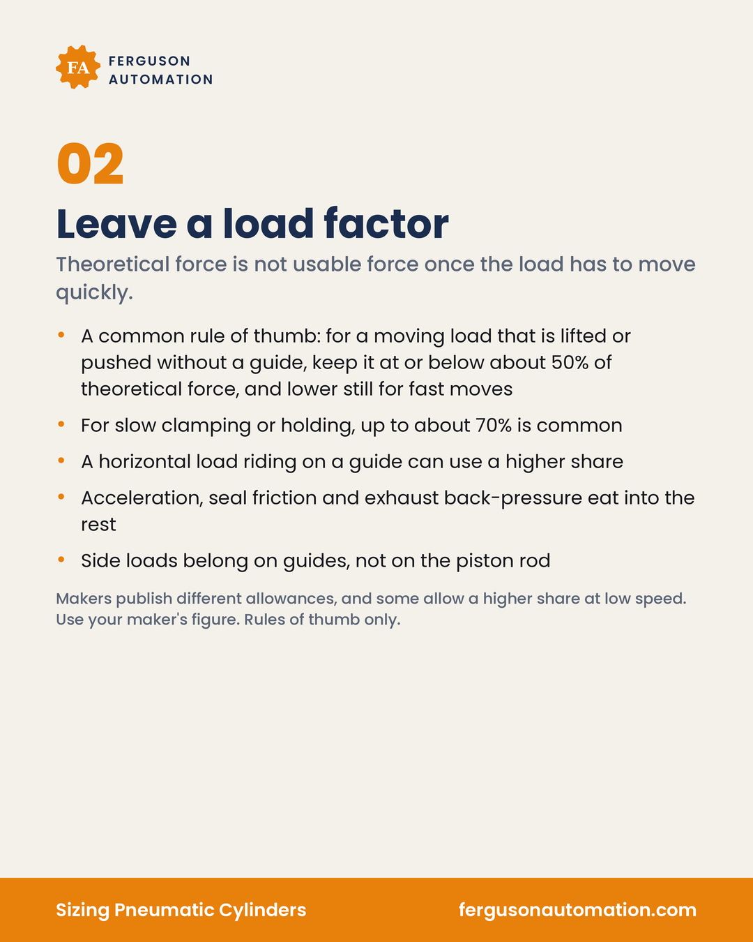
Theoretical force is not usable force once the load has to move quickly. Seal and bearing friction take some of it even before the piston moves. Once it does move, the exhaust side pushes back, and the load has to be accelerated. The load factor is the share of theoretical force you allow the load itself to use.
- A common rule of thumb: for a moving load that is lifted or pushed without a guide, keep it at or below about 50% of theoretical force, and lower still for fast moves
- For slow clamping or holding, up to about 70% is common
- A horizontal load riding on a guide can use a higher share
- Acceleration, seal friction and exhaust back-pressure eat into the rest
- Side loads belong on guides, not on the piston rod
The reserve is what lets the cylinder reach speed. A cylinder sized so the load uses nearly all of the theoretical force may hold the part, but it has little left over to accelerate it. If the load sits off the rod's centerline, or the rod has to carry the weight of tooling, put that load on a guide, a guided cylinder or a slide. Misalignment and side loading wear the rod bearing and cost force.
Makers publish different allowances, and some allow a higher share at low speed. Use your maker's figure. Rules of thumb only. Check the cylinder maker's sizing tools.
Air consumption
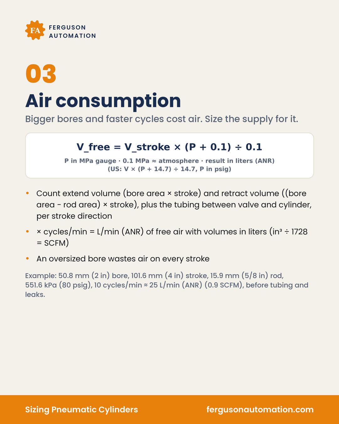
Bigger bores and faster cycles cost air. Size the supply for it.
The air a cylinder uses each stroke is the swept volume, compressed to the working pressure. Converted to free air at atmospheric pressure:
V_free = V_stroke × (P + 0.1) ÷ 0.1, with P in MPa gauge, 0.1 MPa taken as atmospheric pressure, and the result in liters (ANR) of free air when V_stroke is in liters (in US units: V_free = V_stroke × (P + 14.7) ÷ 14.7, with P in psig and 14.7 psi as atmospheric pressure at sea level).
Work it out for each stroke direction:
- Extend volume = bore area × stroke
- Retract volume = (bore area − rod area) × stroke
- Add the tubing between the valve and the cylinder. It fills and exhausts every stroke too
- Multiply by cycles per minute for consumption per minute. Volumes in liters give L/min (ANR) of free air (with volumes in in³, divide by 1728 to get SCFM)
Example: a 50.8 mm (2 in) bore, 101.6 mm (4 in) stroke, 15.9 mm (5/8 in) rod, at 551.6 kPa (80 psig) and 10 cycles per minute, uses about 25 L/min (ANR) of free air (about 0.9 SCFM), before tubing and leaks.
An oversized bore wastes air on every stroke. Consumption scales directly with piston area, so a bore chosen "just to be safe" costs compressed air every cycle for the life of the machine. Leaks and the tubing volume come on top of the cylinder figure, and the compressor needs capacity beyond the calculated total.
Cushioning
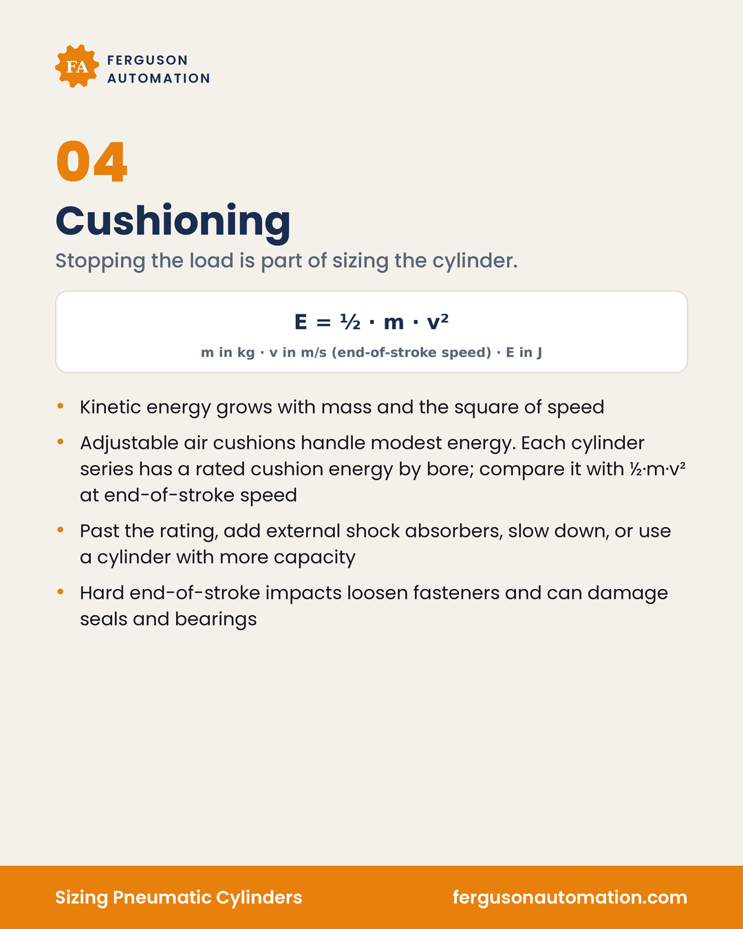
Stopping the load is part of sizing the cylinder.
- Kinetic energy grows with mass and the square of speed: E = ½ · m · v² (m in kg, v in m/s, E in J). Double the speed and the energy to absorb goes up four times
- Adjustable air cushions handle modest energy. Each cylinder series has a rated cushion energy by bore; compare it with ½·m·v² at end-of-stroke speed
- Past the cylinder's rated energy, add external shock absorbers or slow down. A cylinder with more cushion capacity is another option
- Hard end-of-stroke impacts loosen fasteners and mounting hardware, and can damage seals and bearings
Check the cushion against the speed at the end of the stroke, not the average speed. Air cushions also need to be adjusted at installation so the load comes to a smooth stop without bouncing, and may need readjusting over the cylinder's life.
Electric or air?
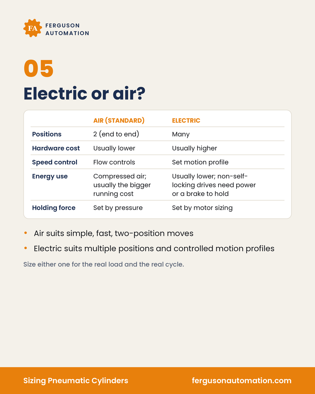
| Air (standard cylinder) | Electric | |
|---|---|---|
| Positions | 2 (end to end) | Many |
| Hardware cost | Usually lower | Usually higher |
| Speed control | Flow controls | Set motion profile |
| Energy use | Compressed air; usually the bigger running cost | Usually lower; non-self-locking drives need power or a brake to hold |
| Holding force | Set by pressure | Set by motor sizing |
- Air suits simple, fast, two-position moves
- Electric suits multiple positions and controlled motion profiles
A standard cylinder runs end to end, with speed set by flow controls and force set by pressure. It holds its end-position force on pressure alone. Air components usually cost less to buy, and compressed air is usually the bigger running cost. An electric actuator can stop at many positions and follow a set motion profile, with its force set by motor and drive sizing. Its hardware usually costs more. A drive that does not self-lock, such as a belt axis, needs power or a brake to hold position; a self-locking ball screw can hold without power.
From an energy-efficiency standpoint, short strokes, long holding times and high end-position force favor air. Long strokes, short holds and many positions favor electric. Size either one for the real load and the real cycle.
A walkthrough: sizing pass for a cylinder
Use this as a process check on a new or replacement cylinder. The steps are mechanical. Valve wiring, controls and programming sit outside this article.
- Define the load. Mass of the part, tooling and anything that moves with the rod, plus the force the task needs (push, pull, clamp or press). Note whether the move is horizontal, vertical or on an incline.
- Pick the load factor. About 50% or less of theoretical force for a moving load lifted or pushed without a guide, lower for fast moves; up to about 70% for slow clamping or holding; a higher share for a horizontal load on a guide. Makers publish different allowances, so use your maker's figure.
- Set the working pressure. Use the pressure the regulator can hold at the valve during the move, not the compressor setting. Allow for losses in long or small lines.
- Size the bore. Required bore area = load force ÷ (load factor × pressure) (N ÷ MPa = mm²). Choose the next standard bore up. If the load acts on retract on a single-rod cylinder, use the rod-side area.
- Check side loads and the rod. Put side and moment loads on guides. On long strokes, check the maker's buckling or maximum-stroke data for your mounting style.
- Check stopping energy. E = ½ · m · v² (m in kg, v in m/s, E in J) at the end-of-stroke speed. Compare it with the rated cushion energy for that cylinder series and bore. If it is over, add external shock absorbers, slow the move, or choose a cylinder with more capacity.
- Calculate air use. Extend plus retract free-air volume, plus tubing, times cycles per minute, in L/min (ANR) of free air. Add the other cylinders on the same supply.
- Check the supply. Confirm the compressor and the lines feeding the station can deliver that flow at the working pressure, with room for leaks and other users.
- Decide air or electric. If the move needs many positions or a controlled motion profile, or the stroke is long and the cycle rate high, compare an electric actuator before committing to air.
- Then open the catalog. Confirm the final choice with the maker's force tables, cushion ratings and sizing tools.
Pneumatic cylinder checklist
- Load mass, task force and direction (extend or retract) written down
- Load factor chosen from the maker's figure: about 50% or less for a moving load lifted or pushed without a guide (lower for fast moves), up to about 70% for slow clamping or holding, higher for a horizontal load on a guide
- Force calculated at the pressure at the valve during the move, not the compressor setting
- Retract force checked with the rod area subtracted (single-rod cylinder)
- Side and moment loads carried by guides, not the piston rod
- End-of-stroke kinetic energy (½ · m · v², in J) checked against the series' rated cushion energy for that bore; external shocks or slower speed where it is exceeded
- Air consumption calculated for extend and retract, plus tubing, at the real cycle rate, in L/min (ANR) of free air
- Supply capacity confirmed, with margin for leaks and other users
- Bore not oversized "just in case": every extra square millimeter costs air on every stroke
- Air versus electric reviewed against the number of positions, motion profile, stroke, cycle rate and holding time
When to call for help
Some cylinder problems are a wrong catalog pick. Others come from the system around it: a bore sized at compressor pressure instead of valve pressure, a load factor with no room left to accelerate, a side load riding on the rod, a supply line too small for the flow, or a stop that is harder than the cushion can absorb. A bigger bore alone does not fix those, and it can make the air bill and the end-of-stroke impact worse.
Cylinder too slow, too weak or slamming at the end of the stroke? Tell us about the load, the stroke and the cycle, and we can talk through the bore, force, air use and cushioning, and whether air or electric fits the move. Contact Ferguson Automation