

A cable starts dropping out on one axis. Someone replaces it, and a few months later the new one fails in the same spot. Then an air line on the same axis starts kinking at the end of travel, or a connector works loose at the moving end. The cable was not the problem. The routing was: the bend was too tight, the chain was packed too full, the run sagged or rubbed, or nothing held the line still where it left the chain.
Routing can end up as the last thing designed on a machine, and a poorly routed line wears out early. Moving cables and air lines need the same mechanical design pass as any other moving part: a bend radius they can live with, room to move, a supported path, strain relief at both ends, and a clear path through the whole stroke. This article walks through that pass. The figures below come from published cable, tubing and cable-chain manufacturer data. Your own suppliers' data governs.
Ferguson Automation is based in Braselton, GA, and works with plants and machine builders across the Southeast on mechanism design, reverse engineering and related mechanical work. The same check applies whether you are laying out a new axis or chasing a cable that keeps failing.
Respect bend radius
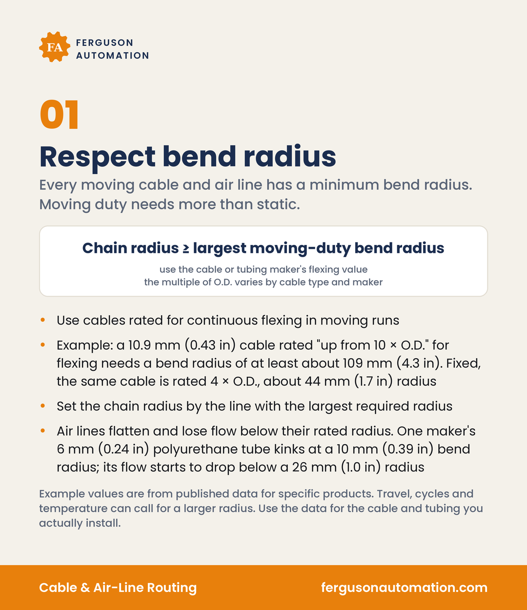
Every moving cable and air line has a minimum bend radius, and moving duty needs more than static.
Chain bend radius ≥ the largest moving-duty bend radius of anything in the chain
- Use cables made and rated for continuous flexing in moving runs. Standard cables that are not designed for continuous flexing can corkscrew and break conductors when they are cycled through a tight radius
- Set the chain radius from the cable maker's moving-duty (flexing) radius, which is often given as a multiple of the cable's outside diameter. The multiple varies by cable type and maker
- Set the chain radius by the cable or hose with the largest required radius, then pick the next chain radius option at or above it
- Air lines flatten, kink and lose flow below their rated radius
Example: one continuous-flex control cable with a 10.9 mm (0.43 in) outside diameter is rated "up from 10 × O.D." when flexing, so its bend radius in a chain is at least about 109 mm (4.3 in). The same cable installed fixed is rated for 4 × O.D., about 44 mm (1.7 in). The chain radius has to suit the moving figure, not the fixed one. The same maker's bending-cycle table can require more: its guide values run from 10 up to 14.5 × O.D., with the higher figures for travel over 10 m (33 ft) or for temperatures at or below 15 °C (59 °F) or above 50 °C (122 °F). Check the maker's cycle and travel data for your application.
Where the cable maker's flexing data is not available, one chain maker's rules of thumb are 7.5 × O.D. for high-flex cables and 10 × O.D. for standard continuous-flex cables, as a minimum. Use the real data whenever you have it.
Tubing data works the same way. One maker's 6 mm (0.24 in) polyurethane tube kinks at a 10 mm (0.39 in) bend radius, but its flow already starts to drop below a 26 mm (1.0 in) radius. Another maker notes that its published minimum bending radius assumes static piping, and that tube used in a moving part needs extra tube length and a check of the bend radius the chain maker recommends. Tube figures vary by maker and material, and makers measure them in different ways, so compare like with like. When tubing runs in a chain, use the tubing and chain makers' figures for moving use, and stay above the radius where flow starts to drop.
Don't overfill the chain
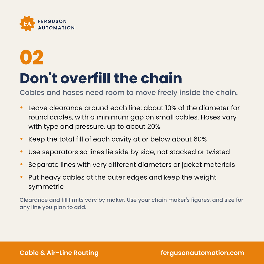
Cables and hoses need room to move freely inside the chain.
- Leave clearance around each line. A common figure is about 10% of the diameter around round cables, with a minimum gap on small cables. Hose figures vary with type and pressure, from about 5% up to about 20%
- Keep the total fill of each cavity at or below about 60% of the cavity area
- Use separators so lines lie side by side, not stacked or twisted around each other
- Separate lines with very different diameters or different jacket materials, so they do not tangle or stick together
- Put heavy cables at the outer edges and keep the weight symmetric across the width of the chain
Example: the 10.9 mm (0.43 in) cable above needs a space about 12 to 13 mm (0.47 to 0.51 in) wide and high, depending on the chain maker's rule: one adds 10% of the diameter, another asks for at least the diameter plus 2 mm on cables under 20 mm. The cavity height is set by the largest line plus its clearance, and the width by adding up every line, its clearance and the separators.
Lines must not be tied together or fastened to the chain links along the run. They need to move freely through the bend, and packing them too tightly is one of the common causes of cable failure in a chain. Uneven weight wears one side of the chain faster than the other. Clearance and fill limits vary by maker, so use your chain maker's figures. If a line may be added later, include it in the cavity sizing now. Adding lines to a chain that is already at its fill limit is a known cause of cable and chain failure.
Support the run
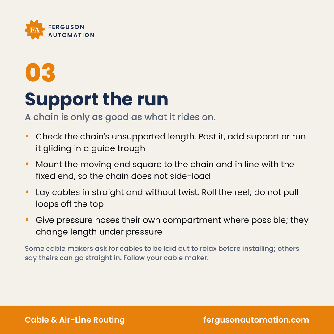
A chain is only as good as what it rides on.
- Check the chain's unsupported length for your fill weight. Past it, add support, or run the chain gliding on itself in a guide trough
- Long travel usually means a gliding arrangement in a guide trough, which keeps the upper run riding squarely on the lower run
- Mount the moving end square to the chain and in line with the fixed end, so the chain does not side-load. Misaligned mounting brackets cause premature failure
- Lay cables in straight and without twist. Roll the reel to unwind the cable; do not pull loops off the top of a coil
- Give pressure hoses their own compartment where possible. They grow or shrink in length with pressure, and the bend has to take up that change
Every chain series has a maximum unsupported length that depends on the series and the fill weight, and the chain maker publishes it. A chain past its limit sags until the upper run rests on the lower run, and a gliding chain needs a guide trough to keep it aligned. Cables need enough length for connection and strain relief at both ends. Some cable makers ask for cables to be laid out or hung for at least 24 hours to relax before installation. Others say their chain cables can go straight in if they are unspooled correctly and laid in without twist. Follow your cable maker.
Strain relief
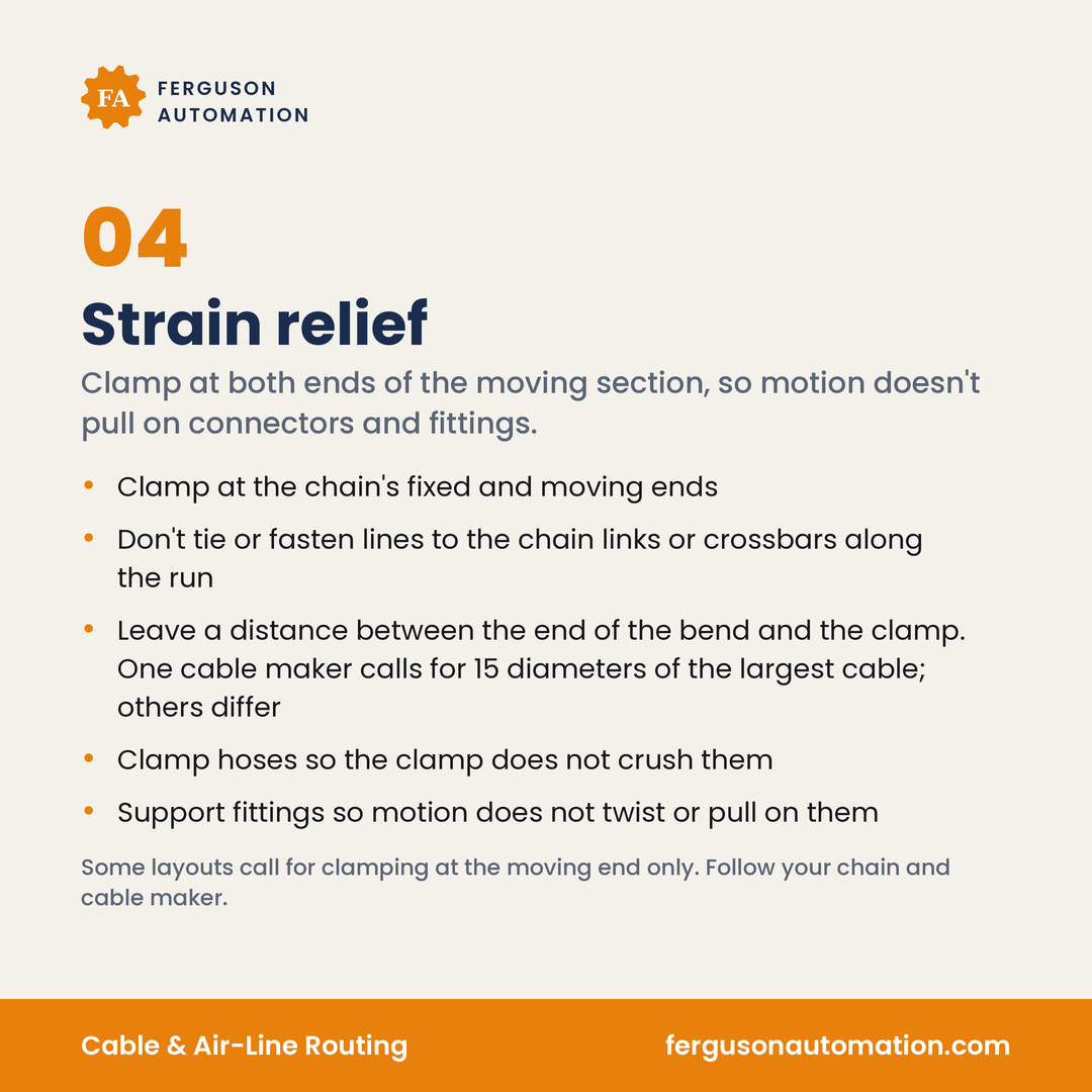
Clamp at both ends of the moving section, so motion doesn't pull on the connectors and fittings.
- Clamp at the chain's fixed end and moving end, so the length of each line inside the chain stays the same
- Don't tie or fasten lines to the chain links or crossbars along the run. Clamp only at the ends unless your chain maker says otherwise
- Leave a distance between the end of the bend and the clamp. Clamp distance varies by maker: one calls for 15 diameters of the largest cable in the chain, another recommends 10 to 30 diameters for most cables but lets its own chain cables be clamped right at the mounting bracket. Follow your cable maker
- Clamp hoses with clamps that will not crush them
- Support fittings and connectors so the motion does not twist or pull on them
Example: at 15 diameters, a chain whose largest cable is the 10.9 mm (0.43 in) cable above has its clamps about 164 mm (6.4 in) past the end of the bend.
Some layouts are clamped at the moving end only, such as some circular-motion chains or chains carrying high-pressure hydraulic hoses. For chains that glide on themselves, one cable maker recommends fastening the cable at the moving end only, with a small reserve of cable at the fixed end, and following the chain maker's assembly instructions. Before final clamping, move the axis to each end of travel and check that every line lies in the bend without being pulled tight against the inner radius or pushed against the outer one.
Keep clear of motion
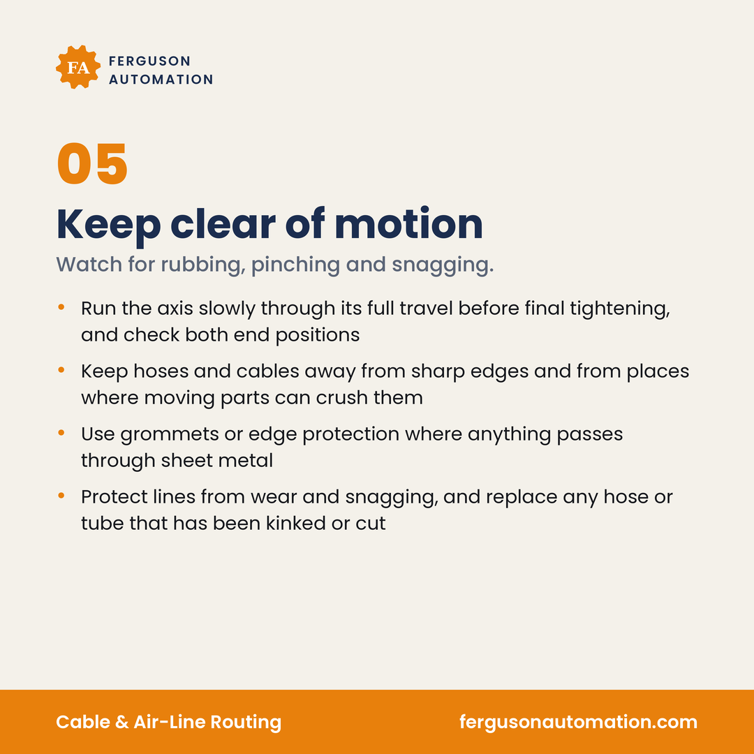
Watch for rubbing, pinching and snagging.
- Run the axis slowly through its full travel before final tightening, and check both end positions
- Keep hoses and cables away from sharp edges and corners, and from places where moving parts can crush them
- Leave the chain a clear path over its whole operating length, width and height
- Use grommets or edge protection where anything passes through sheet metal
- Protect lines from wear and snagging. Replace any hose or tube that has been kinked, bent tighter than its minimum radius, or cut
The first slow run is when to make adjustments to chain position, alignment and line length, before everything is tightened down for full speed. These are practical routing checks for the mechanical design. They are not a machine safeguarding review.
A walkthrough: routing pass for a moving axis
Use this as a process check on a new axis or on one where lines keep failing. The steps are mechanical. Electrical cable selection, wiring and controls sit outside this article.
- List every line. Each cable and hose that moves with the axis, with its outside diameter, its weight and its moving-duty bend radius from the maker's data.
- Confirm the lines are rated for the motion. Continuous-flex cables and chain-rated tubing in the moving section.
- Set the chain radius. At or above the largest moving-duty radius in the list, checked against the maker's data for your travel and temperature.
- Size the cavity. Add clearance around each line, add separators, and keep the fill at or below the chain maker's limit (often about 60%). Include any line you expect to add later. Place heavy lines at the outer edges and keep the weight symmetric.
- Check support. Compare the travel and fill weight with the chain's unsupported length. Add support, or plan a gliding arrangement in a guide trough.
- Lay out the mounting. Moving end square to the chain and in line with the fixed end, with a clear envelope over the whole travel.
- Plan strain relief. Clamps at both ends (or as the cable and chain makers direct for your layout), at the distance the cable maker calls for, with hose clamps that do not crush.
- Install. Unspool without twist, lay lines side by side, and follow the cable maker's preparation instructions.
- Run it slowly. Cycle the full travel, check both end positions, and adjust before final tightening.
- Check the path. Look for sharp edges, crush points, rubbing and snag points, and protect pass-throughs in sheet metal.
Routing checklist
- Every moving cable and hose listed with diameter, weight and moving-duty bend radius
- Continuous-flex cables and chain-rated tubing in the moving section
- Chain radius at or above the largest moving-duty radius, not the static one
- Air lines kept above the radius where flow starts to drop, not just above the kink radius
- Clearance around each line and cavity fill within the chain maker's limits (often about 60%), including any planned additions
- Separators between lines of different size or jacket material; lines side by side, not stacked or twisted
- Heavy lines at the outer edges; weight symmetric across the chain
- Unsupported length checked against travel and fill weight; support or guide trough where needed
- Moving end square to the chain and in line with the fixed end
- Strain relief at the cable maker's distance; nothing tied to the chain links along the run
- Pressure hoses with room for length change
- Full travel run slowly and both end positions checked before final tightening
- Sharp edges, crush points and sheet-metal pass-throughs protected
When to call for help
Some routing problems are a wrong cable. Others come from the layout around it: a chain radius set by the static figure, a cavity packed past its limit, a run that sags past its unsupported length, a moving end that is out of line, or a clamp placed closer to the bend than the cable maker allows. A new cable alone does not fix those, and it usually fails in the same place.
Cables or air lines failing in a moving axis? Tell us about the travel, the lines and where they fail, and we can talk through the bend radius, chain fill, support, strain relief and the path through the stroke. Contact Ferguson Automation