

An axis stalls on a heavy part. Someone swaps in a bigger motor, the move works for a while, and then the gearbox runs hot, the belt slips, or the next cycle rate makes the motor trip on thermal. The catalog rating looked fine. The load numbers were wrong.
Sizing misses often start with the load, not the motor. Before you open a catalog, write down every force the axis has to fight, the real motion profile and the reflected inertia at the motor shaft. This article walks through that mechanical pass: peak torque, RMS torque over the full cycle, inertia ratio through gearing or belts, and gearbox checks with margin. The numbers below follow published manufacturer guidance. Your motor and gearbox maker's sizing data governs.
Ferguson Automation is based in Braselton, GA, and works with plants and machine builders across the Southeast on mechanism design, reverse engineering and related mechanical work. The same load-first check applies whether you are specifying a new axis or replacing a drive that keeps overheating.
Start with the load
Write down every force the motor has to fight before you open a catalog.
- Load mass, plus the tooling, carriage and fixtures that move with it
- Friction, gravity on vertical or inclined axes, and process forces
- The real motion profile: distance, move time, dwell and cycle rate
- Worst case, not typical: heaviest part, coldest grease, longest stroke
Peak torque is often set by acceleration, not by the steady load. A light load that has to start and stop in a short move can need more peak torque than a heavier load that crawls. Dwell matters too. A short dwell and a high cycle rate raise the heat the motor has to shed over the whole cycle, even when each move looks easy on paper.
Torque has parts
Peak torque is the sum of the pieces that act at the same time:
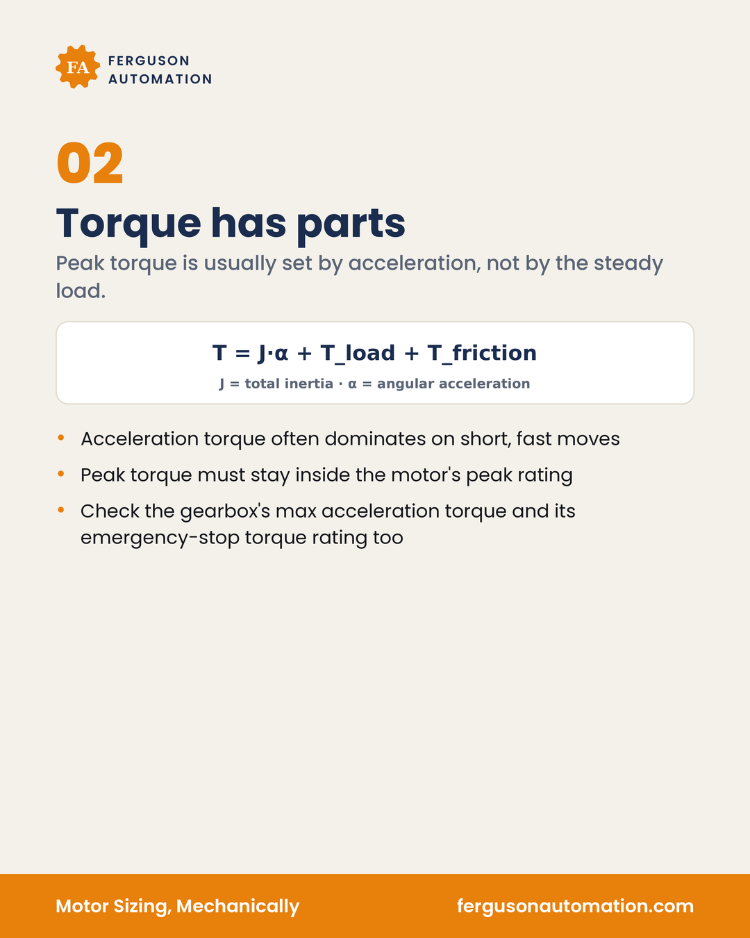
T = J · α + T_load + T_friction (all terms at the motor shaft)
J is total inertia at the motor shaft (motor rotor + gearbox/coupling + load reflected as J_load ÷ i²), in kg·m². α is angular acceleration at the motor shaft in rad/s², α = Δω ÷ t_accel, with ω in rad/s (rpm × 2π ÷ 60). T_load (gravity and process forces) and T_friction are referred to the motor shaft as T ÷ (i · η), where η is drive-train efficiency. All torques in N·m. On short, fast moves, acceleration torque often dominates.
- Peak torque must stay inside the motor's peak (intermittent) rating at your operating speed
- Check normal peaks against the gearbox's max acceleration torque. The emergency-stop torque rating covers rare stop events, not every cycle
- Read both on the maker's torque-speed curve, not from a single catalog number
- Steppers: torque drops with speed, so check the required torque at operating speed against the maker's pull-out torque curve, with margin. Do not size from holding torque. Stepper inertia-ratio guidance varies by maker and drive type, so check yours. Losing steps under load is the risk to design around
A motor that can make the peak once can still fail if the continuous (RMS) demand over the cycle is too high. Peak and continuous are two different checks.
Mechanical power P = T · ω (W, with T in N·m and ω in rad/s) is a useful sanity check against motor rated power at speed.
RMS torque sets heat
A motor that survives the peak can still overheat over the whole cycle. RMS torque is how you compare a varying duty to the motor's continuous rating:
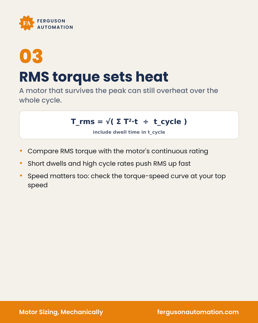
T_rms = √( Σ(T_i² · t_i) ÷ Σ t_i )
Σ t_i is the full cycle time: accel, run, decel and dwell. Leaving dwell out makes the RMS look better than the motor will see on the floor. On vertical axes, holding torque during dwell counts toward the RMS.
- Compare RMS torque with the motor's continuous rating
- Short dwells and high cycle rates push RMS up fast
- Speed matters too: check the torque-speed curve at your top speed
If peaks last a long time compared with the motor's thermal time constant, RMS alone can mislead. Use the maker's duty-cycle data.
Leave margin on both peak and RMS. Published guidance runs from about 20% (servos) to 50% (steppers) above the calculated torque, and some makers use a 1.5–2× safety factor on required and RMS torque (2× for open-loop steppers). That is published guidance, not a design value. The maker's data and your duty cycle still decide.
Inertia ratio
Load inertia, reflected to the motor shaft, compared with rotor inertia:
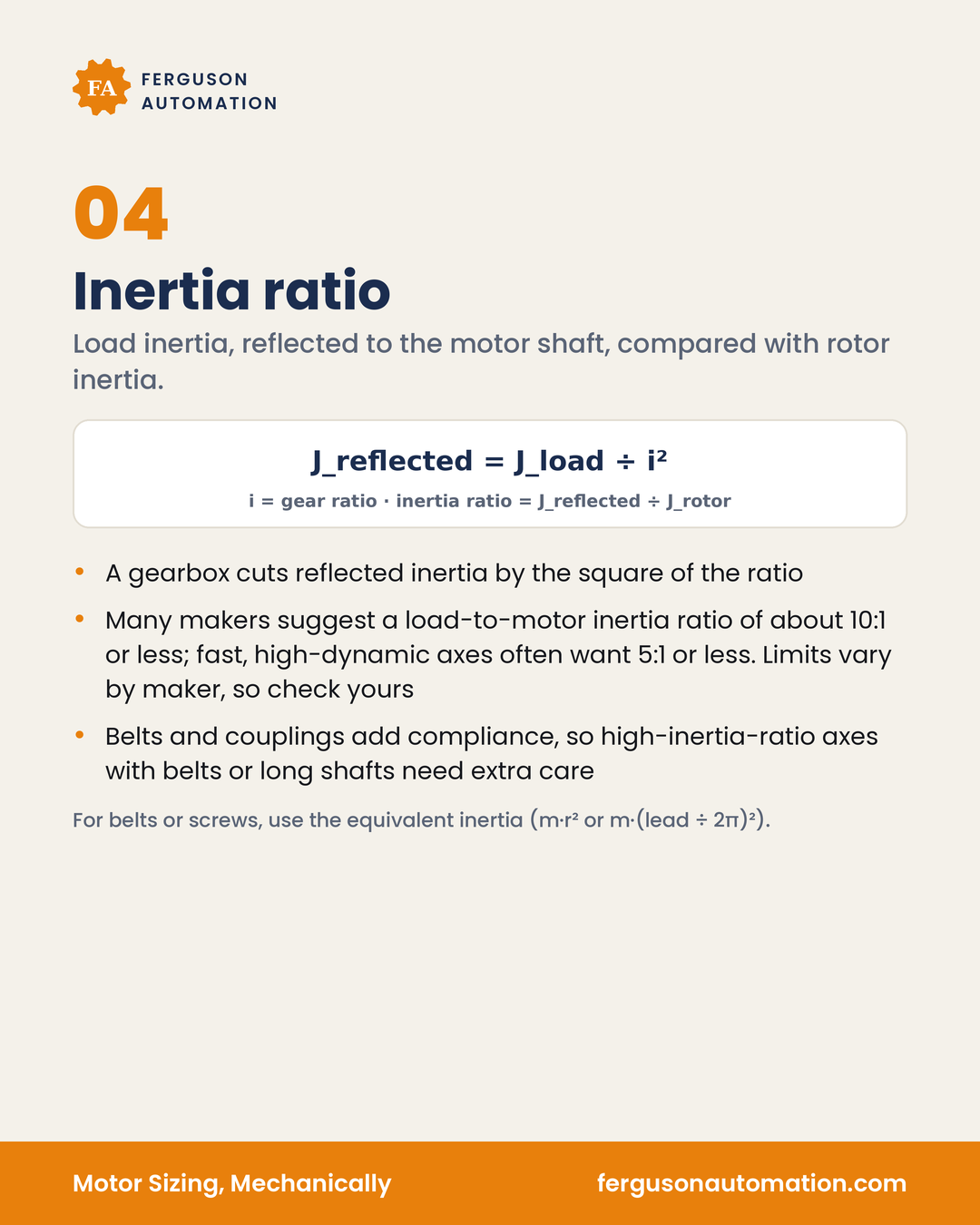
J_reflected = J_load ÷ i²
inertia ratio = J_reflected ÷ J_rotor
i is the gear (or other) ratio. A gearbox cuts reflected inertia by the square of the ratio, which is why a modest ratio can bring a heavy load into a workable band.
- Many makers suggest a load-to-motor inertia ratio of about 10:1 or less; stiff, direct-coupled axes can often run higher, and belts or long shafts usually want lower. Published limits run from about 5:1 to 30:1 or more depending on motor type and maker. Fast, high-dynamic axes often want 5:1 or less. Limits vary by maker, so check yours
- Belts and couplings add compliance, so high-inertia-ratio axes with belts or long shafts need extra care
- For belts or screws, use the equivalent inertia at the motor shaft. Belt: m · r² (r = drive pulley radius in m), plus the pulley inertias, reflected through any pulley ratio. Screw: m · (lead ÷ 2π)² with lead in m/rev, plus the screw's own inertia (from the maker's data). Masses in kg
Inertia ratio is not a substitute for peak and RMS checks. An axis can pass the ratio and still be short on torque, or pass torque and still be prone to overshoot and vibration if the ratio and drive-train compliance are high.
Gearbox and margin
The gearbox is a load-bearing part, not just a ratio.
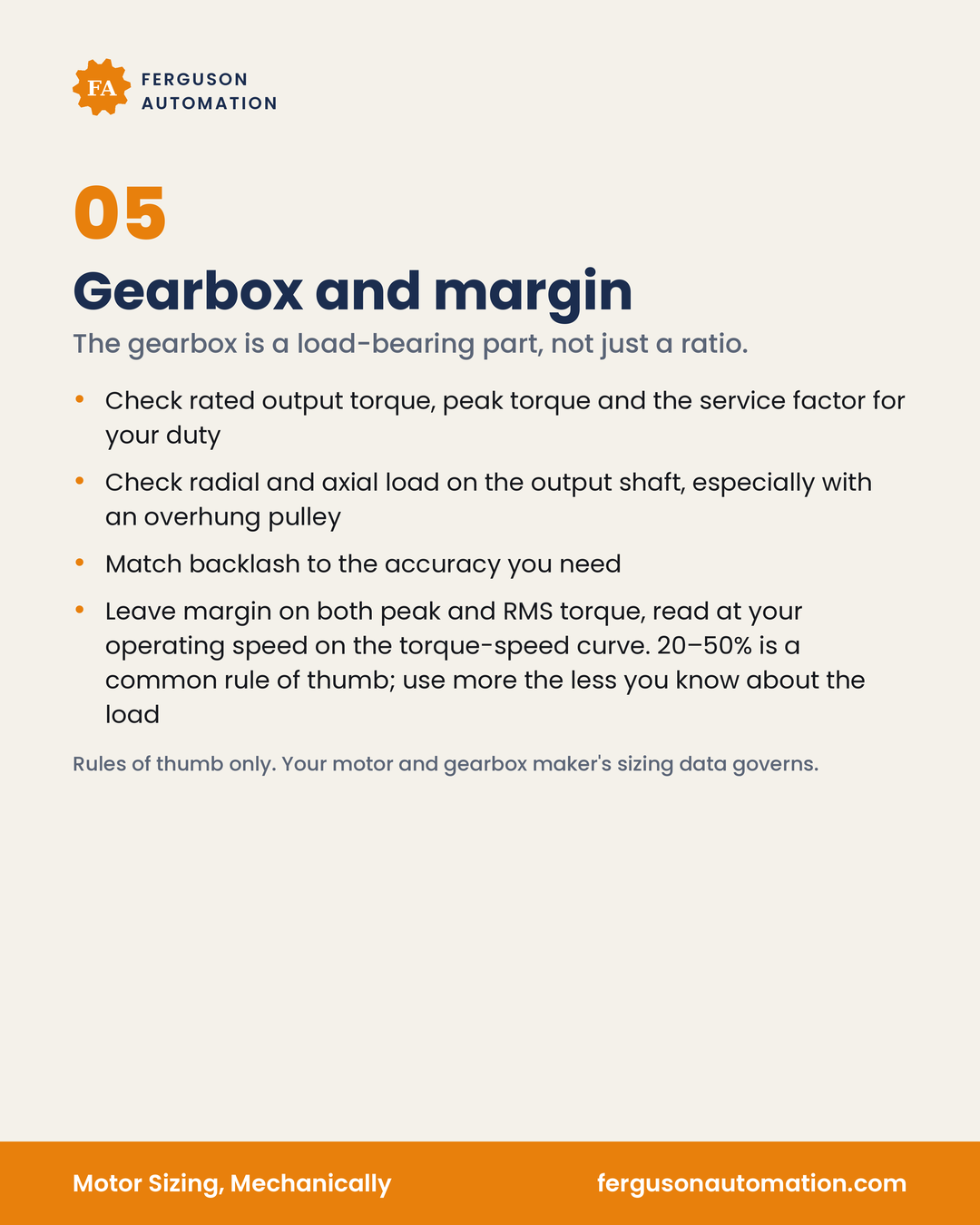
- Check rated output torque, peak torque and the service factor for your duty
- Check radial and axial load on the output shaft, especially with an overhung pulley
- Match backlash to the accuracy you need
- Confirm the efficiency (η) used in the torque reflection, and the gearbox's thermal or continuous-duty rating for your cycle rate and ambient temperature
- Leave margin on both peak and RMS torque, read at your operating speed on the torque-speed curve. Published guidance runs from about 20% (servos) to 50% (steppers) above the calculated torque, and some makers use a 1.5–2× safety factor on required and RMS torque (2× for open-loop steppers); use more the less you know about the load
Rules of thumb only. Your motor and gearbox maker's sizing data governs.
A walkthrough: sizing pass before the catalog
Use this as a process check on a new or replacement axis. The steps are mechanical. Drive setup, tuning and programming sit outside this article.
- List the moving mass. Part, tooling, carriage, fixtures, and anything else that accelerates with the load.
- List the forces. Gravity on vertical or inclined axes, friction, process loads, and worst-case drag (cold grease, full load, longest stroke).
- Write the motion profile. Distance, move time, accel/decel, dwell and cycles per minute. Use the real cycle, not a best-case sketch.
- Check speed. Convert top linear speed to motor rpm (belt: v ÷ (π · d_pulley) × 60 × i; screw: v ÷ lead × 60 × i; v in m/s; d_pulley and lead in m). Confirm it is under the motor's rated or max speed, the gearbox's max input speed, and its nominal input speed for continuous running, and, for screws, the maker's critical-speed limit.
- Reflect inertia to the motor shaft. Convert belt/screw motion to equivalent rotary inertia, then divide by i² through any gearbox (belt: m · r² plus pulley inertias; screw: m · (lead ÷ 2π)² plus the screw's own inertia).
- Compute peak torque. T = J_total · α + (T_load + T_friction) ÷ (i · η) at the worst-case move, with α in rad/s². Compare it to the motor's peak (intermittent) rating at that speed. Compare the gearbox output torque (motor torque × i × η) to the gearbox's max acceleration torque. The emergency-stop torque rating covers rare stop events, not every cycle.
- Compute RMS torque. T_rms = √( Σ(T_i² · t_i) ÷ Σ t_i ), with Σ t_i the full cycle (accel, run, decel and dwell). On vertical axes, holding torque during dwell counts toward the RMS. Compare to continuous rating at your top speed. If peaks last a long time compared with the motor's thermal time constant, RMS alone can mislead; use the maker's duty-cycle data.
- Check inertia ratio. Aim for about 10:1 or less in general; stiff, direct-coupled axes can often run higher, and belts or long shafts usually want lower. Published limits run from about 5:1 to 30:1 or more depending on motor type and maker. Fast, high-dynamic axes often want about 5:1 or less, unless your maker states otherwise.
- Check the gearbox as a load path. Output torque, service factor, radial/axial shaft load, backlash, confirm the efficiency (η) used in the torque reflection, and the gearbox's thermal or continuous-duty rating for your cycle rate and ambient temperature.
- Add margin. Published guidance runs from about 20% (servos) to 50% (steppers) above the calculated torque, and some makers use a 1.5–2× safety factor on required and RMS torque (2× for open-loop steppers); use more when the load is uncertain.
- Then open the catalog. Size to the maker's torque-speed data and gearbox ratings, not to a single nameplate number. Use P = T · ω as a sanity check against rated power at speed.
If the axis still looks marginal after that pass, changing the ratio, lightening the moving mass, softening the motion profile or fixing an overhung load can help as much as, or more than, moving up a motor frame.
Motor sizing checklist
- Every moving mass and force is written down, worst case included
- Motion profile includes move, accel/decel, dwell and cycle rate
- Required motor speed checked against motor, gearbox (max and nominal continuous) and screw limits
- Peak torque checked against motor peak (intermittent) rating at speed and gearbox max acceleration torque (e-stop rating is for rare stops, not every cycle)
- RMS torque includes accel, run, decel and dwell (holding on vertical axes too) and is checked against continuous rating at top speed; use maker duty-cycle data when peaks are long vs thermal time constant
- Reflected inertia and inertia ratio checked (about 10:1 or less; stiff direct-coupled can run higher, belts/long shafts usually lower; published limits about 5:1 to 30:1+; about 5:1 or less for fast axes, per maker)
- Belt or screw equivalent inertia used where the load is linear (m · r² or m · (lead ÷ 2π)², plus pulley/screw inertia; masses in kg)
- Gearbox output torque, service factor, shaft loads, backlash, efficiency (η) and thermal/continuous-duty rating reviewed
- Margin per maker: about 20% (servos) to 50% (steppers), or 1.5–2× on required/RMS torque (2× open-loop steppers) when published
- Final selection made from the maker's torque-speed and gearbox data, with P = T · ω as a power sanity check
When to call for help
Some motor problems are a wrong catalog pick. Others are built into the mechanics: underestimated mass, an inertia ratio that is too high for the compliance in the drive train, an overhung pulley that overloads the gearbox bearing, or a cycle that looks fine on peak torque and fails on RMS. Changing the motor alone does not fix those.
Motor stalls, overheats or keeps getting upsized? Tell us about the axis, the load and the cycle, and we can talk through the mechanical sizing pass. Contact Ferguson Automation