

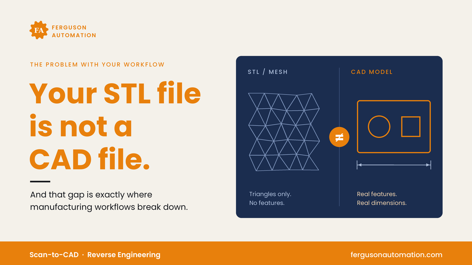
A scan is not a CAD file. And a CAD file is not a finished part. These are three different things, and mixing them up trips up a lot of manufacturing workflows, especially when 3D printing is involved.
Here is where it usually goes wrong. A team scans an existing part, gets a clean STL file and sends it straight to the printer. The part looks right. It prints fine. Then someone needs to change a dimension, machine a mating surface, or check the part against a tolerance stack, and suddenly that STL file is not enough.
This article explains why, and what to do about it.
What a scan actually gives you
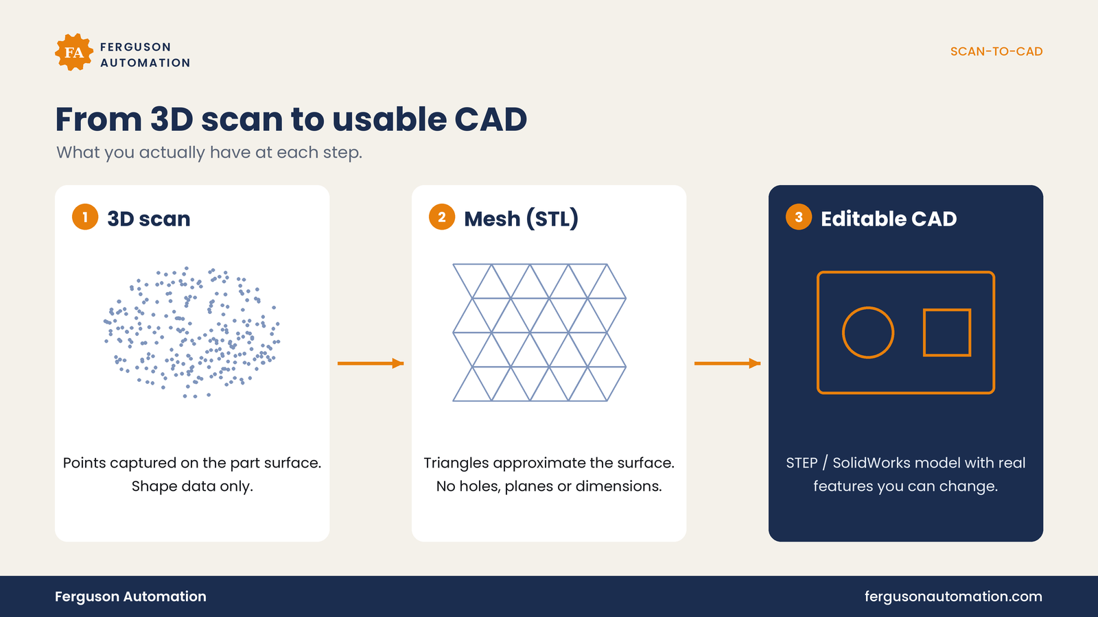
Most 3D scanners capture points on the surface of a part and turn them into a mesh: thousands or millions of small triangles that approximate the surface. That mesh is usually exported as an STL file.
The Library of Congress describes STL as a format for "describing the surface of an object as a triangular mesh," storing only the corner coordinates and an outward normal for each triangle. That is all it holds. There is no hole, no plane, no fillet radius and no dimension. There is no design intent. A mesh approximates shape, but it does not describe it in a way that is useful downstream.
What a CAD model gives you
A solid CAD model describes a part with exact geometry: true planes, cylinders, cones and controlled surfaces, bounded by edges and faces. This is known as boundary representation, the way most mechanical CAD systems store solids. A parametric model adds a feature history: sketches, dimensions and constraints that can be edited later.
That difference matters because a bore in a CAD model is a cylinder with an axis and a diameter. The same bore in a mesh is a ring of flat triangles that only approximates a circle.
CAD can also be exchanged between systems in neutral formats such as STEP (ISO 10303), which carries exact geometry rather than a triangulated surface.
What you cannot do with a mesh alone
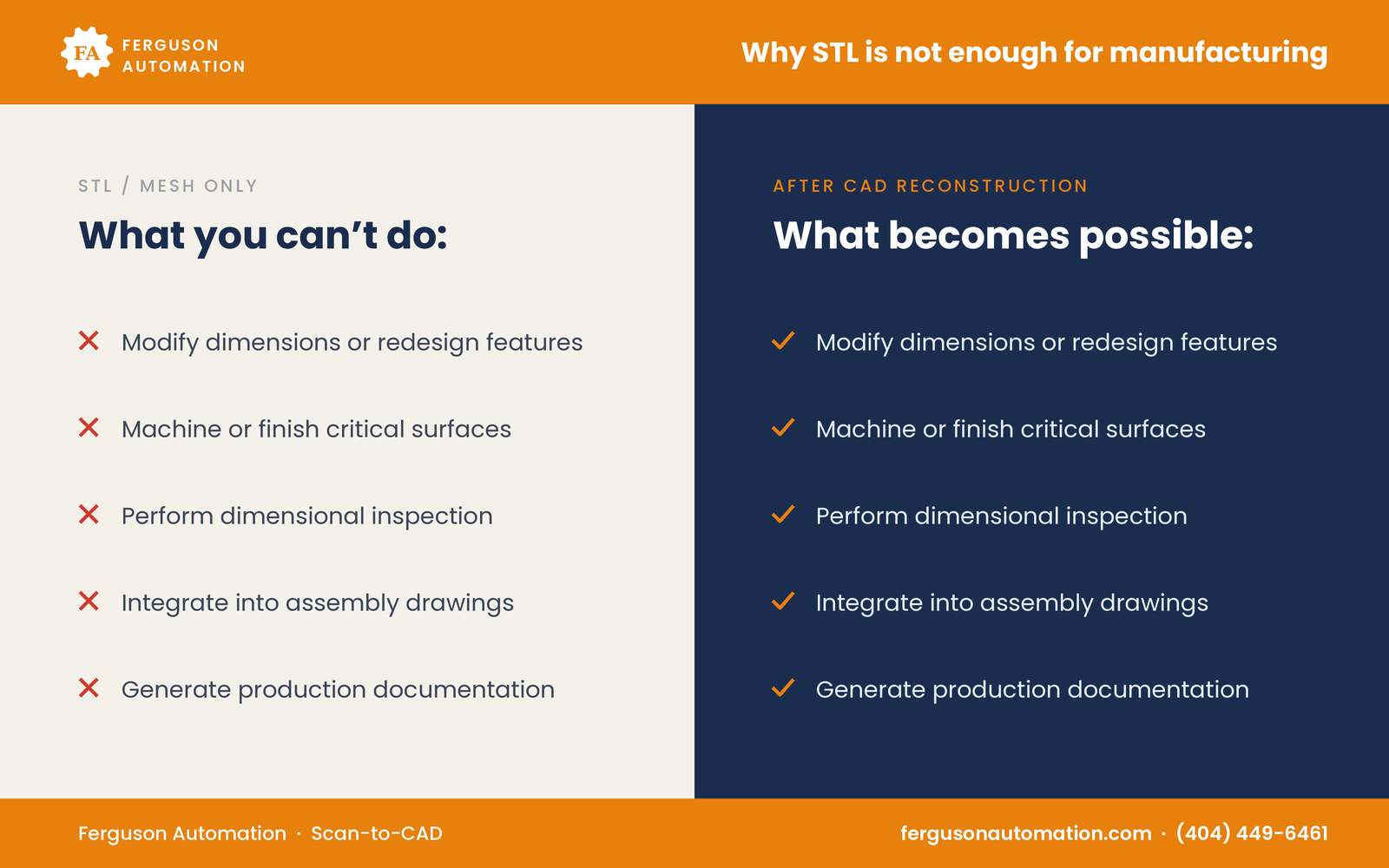
With only an STL or mesh, it is difficult or impossible to:
Modify dimensions or redesign features. There are no features to edit, only triangles.
Machine or finish critical surfaces. CAM programming for precise surfaces needs true geometry, not a faceted approximation.
Perform dimensional inspection against design intent. You can compare a scan to a scan, but inspection needs nominal geometry, datums and tolerances. Dimensioning and tolerancing standards such as ASME Y14.5 are written around nominal features, not meshes.
Integrate into assembly drawings. Mates and constraints in an assembly need real faces, axes and planes.
Generate production documentation. A drawing a machine shop can quote and make from needs dimensions and tolerances.
What CAD reconstruction makes possible
The step that connects scan data to all of that is CAD reconstruction, also called scan-to-CAD or reverse engineering. The raw scan becomes a reference, and the part is rebuilt as a proper CAD model.
Reverse engineering software supports two main approaches. Hexagon's Geomagic documentation describes parametric modeling, where sketches and features are created using the mesh as a reference, and surfacing, where NURBS surfaces are fit to the mesh. Hexagon describes the aim as turning 3D scan data into "feature-based, editable 3D models" that work with other design software.
In practice, most mechanical parts are best rebuilt parametrically:
Scan and clean. Capture the part and remove noise and stray data.
Align to datums. Set up a coordinate system based on how the part is located and how it functions, not on how it sat on the scanner.
Extract features. Identify planes, holes, bosses and other regular features in the scan.
Rebuild with design intent. Model the part with real dimensions and relationships. A hole that measures slightly off a standard size is usually meant to be that standard size; worn surfaces are rebuilt to their original shape, not the worn one.
Compare to the scan. Check the CAD model against the scan data to confirm the reconstruction is faithful where it should be.
Document. Produce drawings, tolerances and file formats for whoever makes the part next.
After reconstruction, you can modify dimensions, machine critical surfaces, inspect against nominal, integrate into assemblies and create production documentation. Everything the mesh could not do.
When a mesh is enough, and when you need CAD
A mesh is often enough when
You only need to print a non-critical copy of a part, as-is
The part is decorative, ergonomic or organic, with no tight fits
You are documenting the current condition of a part or tool for reference
You want a visual check or a rough comparison between two physical parts
You need CAD reconstruction when
The part will be machined, or has mating or sealing surfaces
Anything needs to change: dimension, material, wall thickness, mounting
The part must be inspected against tolerances
It goes into an assembly model or onto a drawing
The original was worn, damaged or never had a drawing, and you need to restore design intent
You want a digital spare you can re-quote, re-make or improve later
Honest limitations
A scan is only as good as the capture. Shiny, dark or transparent surfaces, deep pockets and internal features can be hard to scan. Some features may need to be measured by hand.
A scan captures the part as it is, not as designed. Wear, damage and manufacturing variation all show up in the mesh. Rebuilding design intent takes engineering judgment, and some decisions should be confirmed with the person who knows how the part is used.
Reconstruction takes engineering time. Parametric rebuilding is skilled work, not an automatic export. Fully automatic surfacing can produce a closed model quickly, but it typically lacks the editable features, true planes and cylinders that machining and inspection need.
Material and process are separate questions. A good CAD model tells you the shape. It does not tell you what the part was made of, how it was heat treated, or what loads it carries. Those need to be confirmed separately before a replacement goes into service.
Quick checklist before you scan
What will happen to the part after the scan: print, machine, inspect, redesign?
Which features are critical: bores, mating faces, threads, datums?
Is the part worn or damaged where it matters?
Do you need an editable parametric model, a STEP file, a drawing, or all three?
Who will verify fit and function of the first part made from the new model?
Work with Ferguson Automation
Ferguson Automation is a mechanical design and engineering firm in Braselton, GA, serving metro Atlanta and the Southeast. We bring 3D scanning, reverse engineering, CAD modeling and additive manufacturing together, so a scan becomes a model you can actually machine, inspect and improve. If you have hit the "STL is not enough" wall, reach out. It is exactly the kind of problem we solve.
Visit fergusonautomation.com or call (404) 449-6461.
Have a scan, a worn part, or a part with no drawings? Tell us about it and we can talk through whether scan-to-CAD makes sense for your part. Contact Ferguson Automation, or learn more about our laser scanning and reverse engineering services.