

Workholding can make or break a machining operation, yet it is often treated as an afterthought. When a part has complex geometry, thin walls or a cosmetic surface that cannot be marked, a standard set of flat vise jaws can introduce risk exactly where you least want it: a part that shifts mid-cut, a wall that bows under clamp pressure, or a finished face with jaw marks on it.
Custom soft jaws are the classic answer. Traditionally they are machined from aluminum or mild steel blanks to match the part. That works, but it takes machine time and programming time away from production parts. 3D printed soft jaws are another option: the jaw insert is designed directly from the part's CAD model and printed, so the machine stays free to cut parts.
This article explains where printed soft jaws make sense, where they do not, and how we approach them at Ferguson Automation.
What a soft jaw actually does
A fixture's job is to locate the part, support it and hold it while it resists the forces of the operation, without the part deflecting, moving or rotating more than the tolerance allows. Formlabs' white paper on manufacturing aids frames this in terms of degrees of freedom: a rigid body has six, and a good fixture constrains them without over-constraining the part.
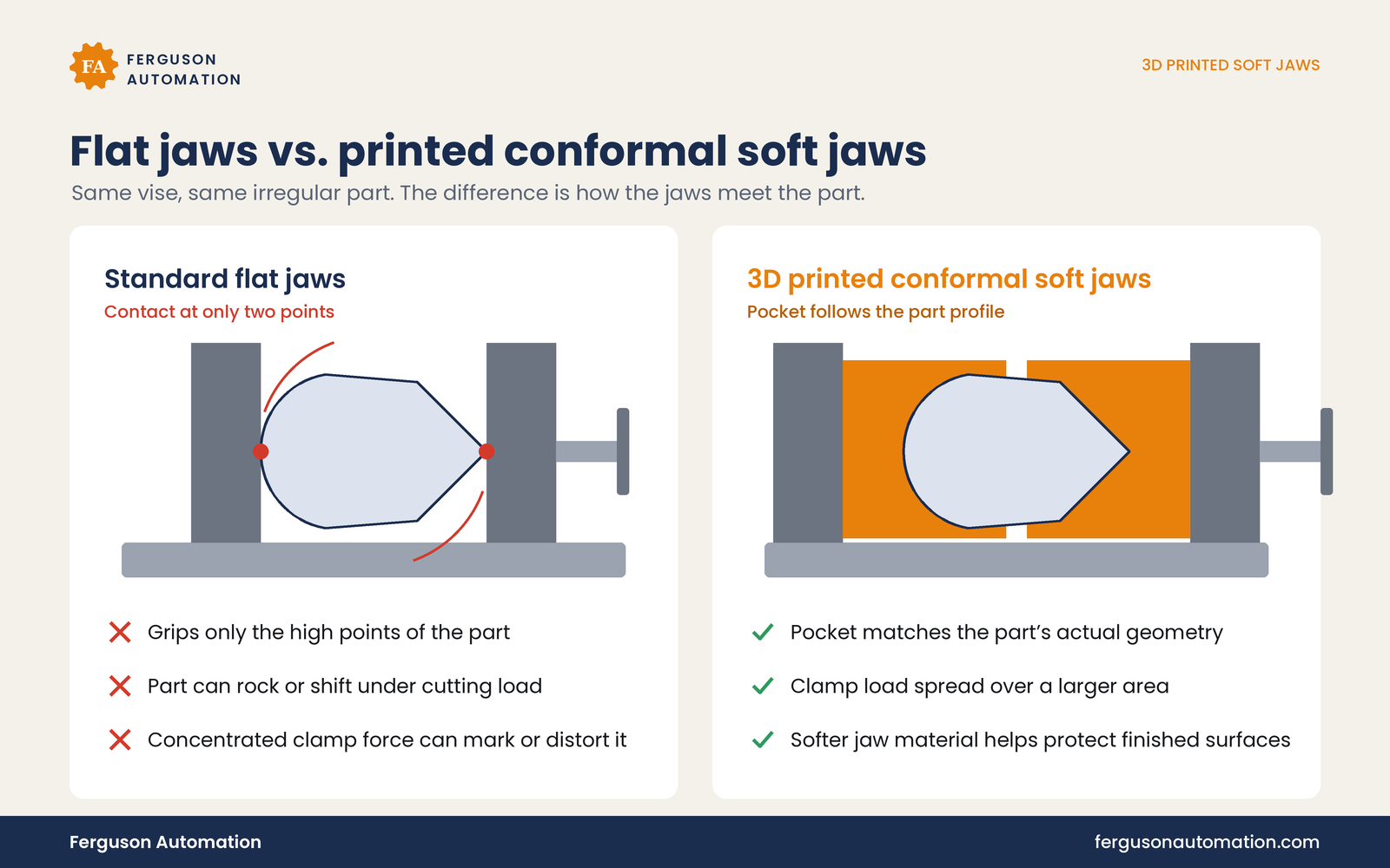
Soft jaws do this by matching the part's shape. Instead of two flat faces squeezing on a few high points, a conformal pocket spreads the clamp load over a larger area and supports features that would otherwise be unsupported. Formlabs describes soft jaw inserts as "customized to closely match the unique geometry of a particular part," allowing complex parts to be held and preventing marring of softer metal or plastic parts.
Three problems printed soft jaws are good at
1. Complex or irregular geometry
Castings, contoured parts, parts with angled faces and second-op parts with features already machined are hard to hold square in flat jaws. Because a printed jaw is generated from the part model, the pocket can follow curves, steps and angles that would be slow to machine into a metal jaw blank.
2. Thin walls and deformation
Thin-walled parts can distort under clamp load. When that happens, the part may measure fine in the vise and spring out of tolerance when released. A conformal jaw that supports the wall over more of its surface reduces local pressure. It does not eliminate the need for sensible clamp force, but it gives the part a better chance of staying true while it is being cut.
3. Cosmetic surfaces
Polymer jaws are softer than aluminum or steel parts, so they are less likely to mark finished or anodized faces. For very delicate surfaces, Formlabs lists flexible and elastic resins specifically for "soft jaws, compliant interfaces".
How we design a printed soft jaw
Every job is different, but the workflow is consistent:
Start from good CAD. The jaw is designed around the part model. If there is no model, the part can be 3D scanned and rebuilt as CAD first (see our article on why a scan is not a CAD file).
Design the jaw around the vise. The insert mounts to a standard jaw or jaw plate, so the printed portion only has to carry the part-specific geometry. A hybrid approach, metal jaw blank plus printed insert, keeps the stiff, wear-prone mounting interface in metal.
Define locating surfaces deliberately. Decide which faces locate the part and which only support it. Add clearance where the part should not touch, such as sharp edges, burrs and flash.
Size walls and ribs for the load. Formlabs' general guidance for printed tooling is to increase rigidity with reinforcing ribs and fillets and to avoid overly thin or unsupported features.
Choose the material for the job. Stiff, tough materials for general holding, softer materials for cosmetic faces, and fiber-filled materials where stiffness matters most. The right choice depends on clamp force, coolant exposure and how long the jaws will stay under load.
Validate before production. Check the printed jaw against the CAD model, load a part, cut a first article and inspect it. Formlabs recommends inspecting printed tooling against the original CAD and, for higher-force processes like machining, calculating clamping requirements from feeds, speeds, machine power and material.
When to use printed soft jaws, and when not to
Good candidates
Parts with contoured, angled or irregular holding surfaces
Thin-walled parts that distort in flat jaws
Finished or cosmetic faces that must not be marked
Low-volume, high-mix work where a dedicated machined jaw is hard to justify
Second operations where the part must be held on already-machined features
Jaws you expect to reprint later; the CAD file becomes your spare
Poor candidates
Heavy roughing with high cutting forces and high clamp pressure
Jaws that will stay clamped under load for long periods
High-temperature environments, or long exposure to coolants and chemicals the material is not rated for
Very tight locating tolerances that depend on the jaw itself rather than a machined datum
Long production runs where wear on the printed surface will add up
Honest limitations
Printed soft jaws are a tool, not a replacement for every machined jaw.
Strength and stiffness. Printed polymers are much less stiff than aluminum or steel. Under heavy clamp loads a printed jaw can deflect, which shows up as part movement or dimensional error. Keeping the load path through a metal jaw blank, and the printed section compact, helps.
Creep. Polymers can slowly deform under sustained load. Formlabs notes that SLA resin parts "may experience creep" if continually loaded and recommends metal or hybrid solutions for very high-wear areas. Creep is a general behavior of materials under sustained stress, so do not leave parts clamped in printed jaws longer than needed.
Layer direction. FDM parts are typically weaker between layers than within a layer. Print orientation should put the clamp load across the strong direction.
Accuracy depends on the process. Printed dimensions vary with printer, material and settings. Critical locating features may need to be verified, or machined, after printing.
Wear. Repeated loading and chip contact will wear a printed surface. Inspect jaws regularly and reprint when locating faces are worn.
A quick checklist before you print
Do you have an accurate CAD model of the part (or a plan to create one)?
Which faces locate the part, and which only support it?
What clamp force and cutting forces will the jaw see?
Is coolant, heat or chemical exposure a factor for the material?
How long will the part stay clamped?
How will you verify the jaw and the first article?
Is the mounting interface metal, with the print carrying only the part-specific geometry?
Work with Ferguson Automation
Ferguson Automation is a mechanical design and engineering firm in Braselton, GA, serving metro Atlanta and the Southeast. We design custom workholding, including 3D printed soft jaws and fixtures, from your part's CAD model or from a 3D scan when no model exists. If a part is hard to hold, distorts in the vise or comes out marked, send us the part details and we will tell you honestly whether printed jaws are the right fit.
Visit fergusonautomation.com or call (404) 449-6461.
Fighting an awkward part in the vise? Tell us about it and we can talk through whether 3D printed soft jaws make sense for your setup. Contact Ferguson Automation