

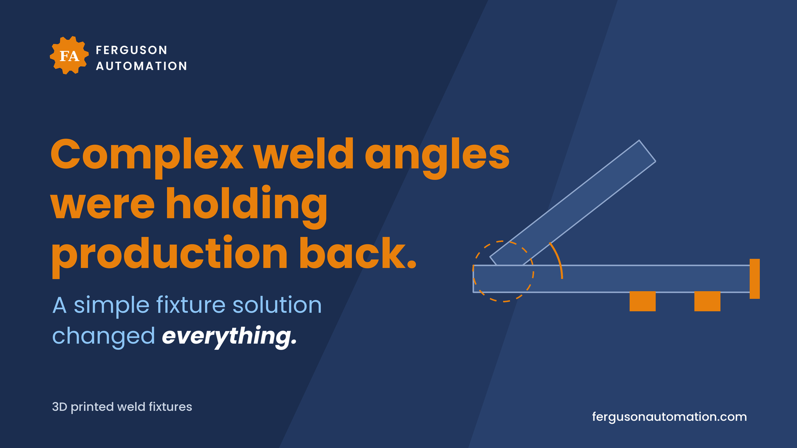
Welding at odd angles should not mean long waits, high fixture costs or guesswork. Yet that is often how it goes. A weldment with compound angles needs a fixture, the fixture has to be machined, and until it arrives, each assembly is laid out by hand with squares, protractors and shims. The result depends on who is welding that day.
In one recent project, Ferguson Automation helped a client rethink how their weld fixtures were made by using additive manufacturing instead of traditional machining. This article walks through the approach, where it works, and where printed fixtures are the wrong tool.
Why traditional fixtures fell short
The client's welded assemblies had angled joints that were difficult to set up consistently. The problems were familiar to most fabrication shops:
Long lead times for machined fixtures
High fixture costs, which made dedicated fixtures hard to justify for lower-volume assemblies
Manual alignment variability between assemblies
Reliance on operator experience to get angles right, which led to inefficiency and rework
None of this means machined steel fixtures are bad. For high-heat, high-volume or heavy-load work they are often the right answer. But for tack-welding fixtures on lower-volume or frequently changing parts, the cost and wait can be out of proportion to the job.
The approach: fixtures designed from the part geometry
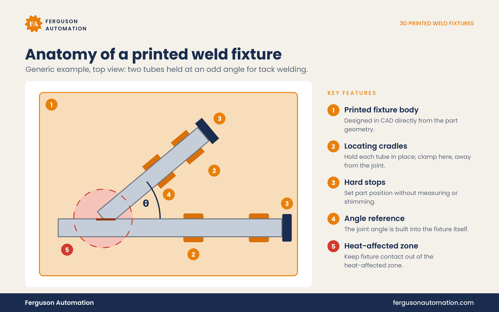
We designed custom 3D printed weld fixtures directly from the part CAD. Because the fixture is generated from the same model as the part, the geometry that controls the weld can be built in rather than set up by hand:
Built-in angle control. The fixture holds each member at the designed angle, so the welder does not measure it.
Hard stops. Parts are pushed against positive stops that set their position along each axis.
Reference surfaces. Datum faces on the fixture match datum features on the part, so every assembly is located the same way.
High-temperature material selected for the heat of tack welding near, but not on, the fixture.
Intuitive design that needs minimal welder training: parts only go in one way.
The goal is simple: parts are loaded, clamped and tacked with confidence, without measuring, shimming or second-guessing. Once tacked, the assembly can come off the fixture for final welding.
What changed
In this project, assemblies consistently met their angular and dimensional requirements, setup time was significantly reduced, and the printed fixtures came in at significantly lower cost than machined steel fixtures. Results depend heavily on the part, the welding process and the material chosen, so treat this as one example, not a promise.
Material matters: heat is the main constraint
Welding arcs are far hotter than any polymer can tolerate, so a printed weld fixture only works when the fixture is kept out of direct contact with the weld and the heat-affected zone. The Fabricator's coverage of printed weld fixtures quotes an applications engineer saying fiber-reinforced fixtures can be used for tack welding "as long as the fixture contact points are out of the heat-affected zone," and that steel supports or clamps at the point of contact can isolate heat.
Material choice should follow the heat. A few published reference points:
In its FDM composite tooling design guide, Stratasys describes ABS-M30/ASA, polycarbonate and ULTEM 9085 tools as effective up to about 82 °C (180 °F), 132 °C (270 °F) and 149 °C (300 °F), respectively.
Formlabs lists a heat deflection temperature of 218 °C at 0.45 MPa for its glass-filled Rigid 10K Resin and recommends it for welding fixtures.
These ratings come from specific test conditions and are far below arc temperatures. They tell you which materials can tolerate radiant heat and short exposure near a tack weld. They do not mean any polymer belongs in the weld zone. In a Formlabs customer example, printed jigs worked because they were "not directly in contact with the weld" and the welding time was short; some blackening still occurred.
Design guidelines we follow
Keep contact points away from the joint. Locate on surfaces well back from the weld, and use metal inserts, pads or clamps wherever a contact must be close.
Design for tacking, not full welding. Tack in the fixture, then finish welding off the fixture or in a steel fixture.
Build in the datums. Angle control, hard stops and reference surfaces should come from the part model.
Make loading obvious. Asymmetric features or poka-yoke details prevent loading parts backwards.
Leave room for the torch and the welder's hands. Access is part of the design.
Plan for wear and spatter. Put replaceable metal wear pads where parts slide in, and expect to reprint fixture bodies over time.
Verify the first article. Inspect the fixture against CAD, then tack and measure a first assembly before relying on it. Formlabs recommends checking seating against locating surfaces and supports during functional testing.
When to use printed weld fixtures, and when not to
Good candidates
Tack-welding fixtures for odd-angle or compound-angle assemblies
Low-to-medium volume parts where a machined fixture is hard to justify
Assemblies that change often or have several variants
Setups that currently depend on layout, measuring and shimming
Check fixtures and go/no-go gauges for welded assemblies
Poor candidates
Full-penetration or long-duration welding with the fixture near the joint
Fixtures that must resist significant weld distortion or heavy clamp loads
Robotic or high-cycle cells where the fixture heats up cycle after cycle
Fixtures that also serve as a heat sink or a ground path
Large, heavy weldments where fixture stiffness is critical
Honest limitations
Heat. Printed polymers soften, discolor or deform with heat. Every material has a limit, and a fixture that sees repeated heat cycles can drift out of position before it visibly fails.
Stiffness and creep. Polymers are far less stiff than steel and can slowly deform under sustained clamp load. Heavy clamping or a part pulling against the fixture as it cools can move a printed fixture.
Spatter and wear. Spatter can pit polymer surfaces, and loading wears locating faces. Inspect and reprint as needed.
Accuracy. Printed accuracy depends on printer, material and settings. Critical datums may need to be verified or fitted with machined inserts.
Not a structural or safety device. A printed fixture locates parts for tacking. It is not a lifting device, a structural support or a guard.
Quick checklist
What welding process is used, and how close to the fixture is the joint?
Is the fixture for tacking only, or for full welding?
Which part features are the datums?
What clamp loads and distortion forces will the fixture see?
How many cycles per shift, and does the fixture have time to cool?
Where do you need metal inserts, pads or clamps?
How will you verify the first assembly?
Work with Ferguson Automation
Ferguson Automation is a mechanical design and engineering firm in Braselton, GA, serving metro Atlanta and the Southeast. We design weld fixtures, jigs and workholding from your part geometry, and we will tell you plainly when a printed fixture makes sense and when steel is the better choice. If your odd-angle assemblies depend on measuring and shimming, let's talk.
Visit fergusonautomation.com or call (404) 449-6461.
Have a weld that’s hard to hold at the right angle? Tell us about it and we can talk through whether a 3D printed fixture makes sense for your job. Contact Ferguson Automation